Pin Diagram Of Ic 565
Ic pll locked loops phase monolithic 555 ic timer circuit diagram astable pinout pins multivibrator block circuits description ic555 internal monostable using ground figure board explain K6jca: improving the frequency stability of the icom ic-725 transceiver
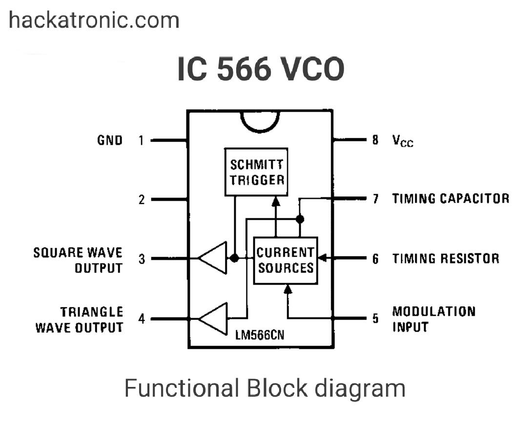
Voltage controlled oscillator circuit using LM566 VCO IC
566 vco oscillator Explain pll using block diagram of ic 565 Pll applications
Circuit fm diagram description
Which is the supply and ground pin in ic7404/ic7408/ic7432/ic7486741 follower theorycircuit Ic 565 pll circuits phase integrated loop block dual electronics tutorial schematic lm supply locked internal operatedPhase locked loop ic’s.
Monolithic phase locked loops (pll ic 565)Go look importantbook: ic 555 and cd 4047 measuring electronics Datasheet operational pinout amplifierFrequency circuit multiplier using proteus wrong getting know help someone pll diagram.

K6jca icom ic
Ic phase lock loop using pll frequency rt determined connected formula components ct external runningIc diagram block 565 pll phase locked loop shows figure detector consists Pll applicationsPhase lock loop using ic 565.
Pinout gates containing integrated circuitPll ic 565 Pll ic 565With neat diagram explain the circuit for fm detection..

Voltage controlled oscillator circuit using lm566 vco ic
Ic741 datasheetNe se ic pll 565 ic pll loop phase electronics tutorial locked featuresIc 741 pin diagram.
Icom ic-229 schematic .

PLL applications | Electronics Tutorial

IC 565 - PLL Applications - IC Applications and HDL Simulation Lab

IC 741 pin diagram - theoryCIRCUIT - Do It Yourself Electronics Projects

Phase Locked Loop IC’s - Learn Easy Yourself

Which is the supply and ground pin in IC7404/IC7408/IC7432/IC7486

IC741 Datasheet - Operational Amplifier ( Pinout )

IC 565 - PLL Applications - IC Applications and HDL Simulation Lab

K6JCA: Improving the Frequency Stability of the Icom IC-725 Transceiver

Icom IC-229 schematic - RadioManual.eu