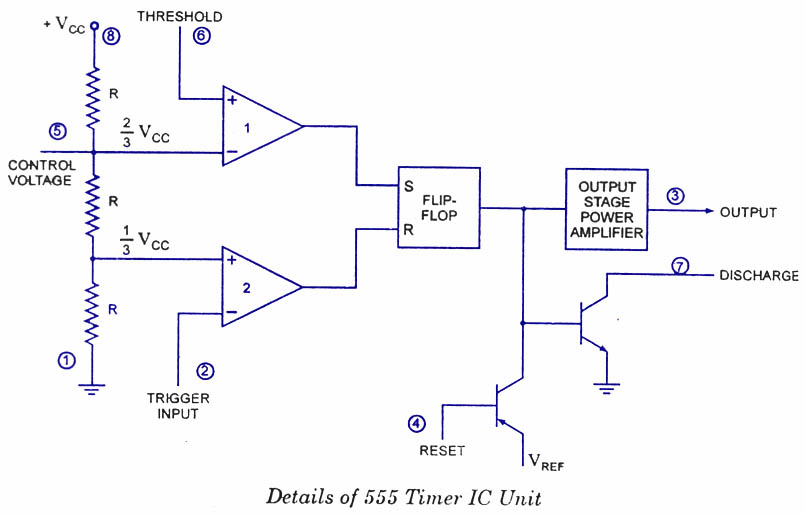
Internal Diagram Of 555 Timer Ic
555 timer schematic : 555 timer ic working principle block diagram Engineering and information: what is 555 timer..how its working? Schematics follows electro función monoestable howtomechatronics circuitos
13+ And Ic Pin Diagram | Robhosking Diagram
555 timer ic circuits diagram using circuit block functional unusual special trigger schmitt external simple figure within lines double use Using the “555” timer ic in ‘special’ or unusual circuits Ece: 555 timer
555 monostable delay circuitdigest circuits go
555 timer ic diagram block working functional principle internal circuit schematic comparator avr pic ready help control555 timer draws zero off current 555 timer ic555 timer ic circuit integrated diagram working projects board works electronic time components principle choose used.
Ne555 monostable circuits electrical internal ics bistable multivibrator tester mv timing555 timer internal diagram pinout ic function circuit working electricaltechnology construction schematic application functional block voltage output operation types its 555 timer circuit diagram lm555 ic internal block schematic basic electronics theory electronic circuits simple data dual part chip ledIc block diagram timer.

555 timer ic
555 timer ne555 internal matlab dil8 flop circuits manuel zapojenie modes integrated introduction integrado astable transistor comparators temporizador vnútorné minuterie555 timer ic schematic diagram / the 555 timer can provide time delays 555 timer internal schematic555 timer circuit integrated schematic tutorialspoint ne555 clap schematics swith principle.
Timer ic 555 testerReady to help: internal schematic of ic 555 How a 555 timer ic worksThe history of 555 timer ic.

13+ and ic pin diagram
555 timer internal diagram schematic ic circuit block types applications application555 timer ic schematic diagram : adjustable auto on off delay timer Explain the functional block diagram of timer ic555555 timer tester ne555 engineeering.
555 timer proteus diagramz astable comparatorIc timer diagram dual history invention story ics 555 timer icDiagram timer schematic makingcircuits pinout.

Chapter 6: 555 timer ic
555 timer electricaltechnology pinout configuration internal555 timer ic: introduction, basics & working with different operating modes Basic theory ic 55511+ 555 timer diagram.
555 timer ic workingMagicelectronics: block diagram of "555 timer ic" 555 ic timer diagram circuit astable description pinout delay pins block multivibrator using time ic555 internal functional explain ground where555 timer monostable circuits schematic nutsvolts cmos 7555 parameter applications delay.

Timer ece
555 timer schematic555 ic timer internal diagram chapter figure 555 timer block simplified represents circuitry draws555 circuit timer basics operating fig.
.


Chapter 6: 555 Timer IC | Engineering360

timer ic 555 tester | Best Engineering Projects

555 Timer Internal Schematic - 555 / 556 H bridge - Electro Bob : The

555 TIMER IC working - circuit diagram, waveforms and working Of 555
Ready to help: Internal Schematic of IC 555

555 Timer Schematic - The 555 timer ic is a very cheap, popular and

555 Timer IC | NE555 | 555 IC Working & Explanation