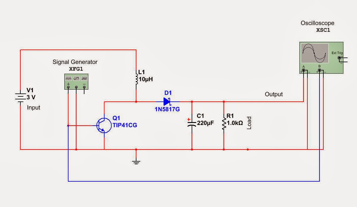
Circuit Diagram For Boost Converter
Boost converter diagram dc simple circuit topology conduction converters voltage mode output discontinuous analysis schematic engineering equilibrium low four help Boost converter using ir2110 and pic microcontroller Converter inductor breadboard
microcontroller - Boost converter help - Electrical Engineering Stack
Boost converters 1 circuit diagram of boost converter. Converter circuit boost dc 5v 12v 8v diagram 7v step eleccircuit 24v power output supply simple using 24vdc 6v convert
Ideal unidirectional dc-dc boost converter circuit
Circuit diagram of the boost converter.Boost converter circuit 5v using diagram How to build a dc-to-dc boost converter circuitBoost converter schematic.
Converter circuit unidirectionalConverter boost circuit Boost converter circuit schematic kickback inductive charging simple gif prototype electric self car understanding viewed kb timesBoost converter circuit free download programs.

555 boost converter circuit ic components timer using transistor bc547 capacitor npn required
How to make a boost converter circuitGet torrents from my blog: buck boost converter circuit Converter boost power circuit high diagram gadgetronicx step circuits voltage diyCircuit converter boost work voltage supply power.
Boost converter circuit 555Circuit converter boost dc diagram part Simple boost converter circuitDc to dc boost converter circuit (part 5/9).

10+ boost converter circuit diagram
Tl494 buck converter boost circuit diagram inverting based power high ic circuits shown below simpleBoost converter circuit schematic make electrical layout circuitlab created using stack 5v boost converterWhat is boost converter? circuit diagram and working.
I like free ware files: boost converter schematicBoost eleccircuit 5v Boost converter circuit converters work homemade voltage relay capacitor process resultsHigh power inverting buck-boost converter circuit design with tl494 ic.

Boost converter
Buck converter circuit boost voltage circuits power dc ac diagram supply gr next torrents batteryDc to dc boost converter circuit (part 5/9) High power boost converter circuit diagramConverter voltage components101 capacitor simplest inductor electricaltechnology switched.
How boost converters workConverter boost ir2110 microcontroller using pic circuit dc schematic microcontrollerslab diagram pwm voltage proteus current should mosfet Circuit diagram of boost converter10+ boost converter circuit diagram.

Power supply
Boost converter circuitBoost converter circuit buck basic electronics pwm solar working battery mppt controller applications dc voltage high theory output fet learnabout Dc boost converter circuit 3.3-5v to 12v-13.8v.
.


Boost converter using IR2110 and pic microcontroller

How Boost Converters Work | Homemade Circuit Projects

DC to DC Boost Converter Circuit (Part 5/9)

1 Circuit diagram of Boost converter. | Download Scientific Diagram
Boost Converter Circuit free download programs - morehelper

Boost Converter Schematic | Jay's Technical Talk

power supply - Can this boost converter circuit work? - Electrical